


Navigation series
GNSS disruptions have long since ceased to be merely a theoretical scenario in the Baltic Sea region. Latest warnings and reports on GPS disruptions show that chartplotters and navigation apps can, at times, fail to provide any position data or provide implausible positions. Those who are proficient in using paper nautical charts, a compass and taking bearings will still be able to cope.
Even without external interference, electronic navigation systems can fail – for example, due to a power cut, a technical fault, water ingress or a lightning strike. Terrestrial navigation is therefore not just exam knowledge, but an essential skill on board. Quite apart from that, there is always a certain appeal in determining one’s current position using simple methods, just as the seafarers of old did.
Find tracking targets
To determine a position, objects with a known position must be within sight. This applies equally to satellite navigation, where the GNSS antenna must have a sufficient number of satellites within its field of view. In terrestrial navigation, these objects are earth-based, such as navigational marks and landmarks. They must be marked on the nautical chart.
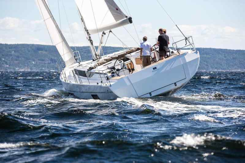
The first step, therefore, is to look out from the cockpit: what can be seen in the ship’s surroundings, and which of the objects spotted are also marked on the nautical chart? Is the distinctive church tower to starboard actually shown there? What about the radio mast visible further ahead? To identify features beyond any doubt, you need to have at least a rough idea of where you are – this is where regular cross-referencing comes in handy.
Some nautical charts and local pilot guides feature drawings or photographs of distinctive landmarks to aid identification. The appearance of lighthouses is also described in the list of lighthouses. At night, lighthouses can be clearly identified by their colour, call sign and period of light.
As a general rule, the more landmarks are included in the positioning process, the more reliable the result will be. However, it is not always the case that several suitable objects will be visible at the same time. Especially as these objects must be stationary. Buoys floating in the water are of limited use. Ultimately, though, you have to make do with what’s available at the time. Any inaccuracies can be corrected when more suitable objects come into view.
From an angle to a line
The simplest way to determine one’s position is by taking a bearing. If, for example, you take a bearing of 120 degrees towards a lighthouse, you must be situated somewhere along a line from which the lighthouse lies exactly in that direction. This is known as a ‘bearings line’. It encompasses all possible positions of the vessel based on a previous measurement.
The position line is plotted on the nautical chart by drawing a line from the lighthouse’s location in the opposite direction to the bearing (bearing value +/- 180°) – in our example, therefore, in the direction of 300 degrees (120° + 180° = 300°). This is because if the lighthouse is at 120 degrees as seen from my position, I must be in the direction of 300 degrees as seen from the lighthouse.
It is important always to use a true bearing (rwP) when making entries on a nautical chart. This is because the nautical chart is oriented to true north (rwN). On sailing yachts, however, bearings are usually taken using a magnetic compass, which is subject to so-called compass errors.
A magnetic compass bearing (MgP) must therefore first be corrected for the deviation (Abl, also known as ‘deviation’) and the magnetic declination (MW), and converted into a true bearing.
Bearing conversion
In order to plot a position line on a nautical chart based on a magnetic compass bearing (MgP), the bearing must first be corrected for any compass errors – that is, for declination (Abl) and magnetic variation (MW; more on these errors in the next instalment). A calculation method has proven effective for this, which many will likely recognise from their training for the recreational boat licence examination:

The direction of calculation is from top to bottom – from ‘wrong’ to ‘right’, the latter always being the direction pointing to the right. The signs are set accordingly. When converting a bearing from a rwP to an MgP, the signs would be reversed.
The value for the deviation, including its sign, is taken from the deviation table for the steering compass when taking bearings with it (where available). Important: The magnetic compass bearing (MgK) at the time of the bearing is the decisive factor, not the bearing (MgP). This is because, for the declination, it makes no difference which direction you take a bearing in using the steering compass – it depends solely on the direction in which the compass is currently aligned. Therefore, the declination value applicable is always that corresponding to the MgK prevailing at the time of the bearing.
As the deviation depends on the compass’s position on board, it remains unknown when taking bearings with a mobile compass (in the absence of better information, a deviation of 0° is assumed in this case).
The following applies to the MW: an eastern value is generally positive (+), whilst a western MW has a negative sign (-).

Distance-measuring device on board
As the deviation depends on the compass’s position on board, a table containing the relevant values usually exists – if at all – only for the steering compass. This actually makes it the preferred navigation tool.
In practice, however, it is usually of limited use, if any at all. For example, with compasses mounted on the steering column, the compass cover and superstructure often get in the way when taking bearings ahead. With a bulkhead compass, taking bearings astern is impossible – unless you alter your course to take the bearing.
You can also try to align the yacht’s keel line precisely with the object being sighted, and then use the resulting magnetic compass bearing (MgK) as the bearing value. This method also works with an electronic compass, which can be compensated for relatively easily to completely eliminate magnetic deviation. GPS, on the other hand, is not suitable for this purpose, as it has no reference to a true north alignment.
If you do not wish to alter your course whilst taking a bearing, a hand-held bearing compass or a pair of marine binoculars with a built-in compass are suitable options. These are also subject to deviation, although the extent of this is unknown. You will therefore have to accept a corresponding margin of error in the bearing.
A bearing disc offers an alternative solution. It is used to take lateral bearings (SP). The angle read off the disc therefore refers to the yacht’s true heading (bow direction). It is added to the current heading to give a north-referenced value (MgK + SP = MgP; if the bearing is to port, the value must be subtracted). This allows bearings to be taken in all directions, taking into account the deviation of the steering compass.
A location at the crossroads
Once we have plotted the position line on the nautical chart, we already know that we are somewhere along that line. To determine our exact position, we need at least one more position line – ideally from a second bearing object. The ship’s position lies at the point where these lines intersect.
For a cross-bearing of this kind, the two bearing objects should not be too close together; otherwise, the lines will overlap, meaning that no clear point of intersection can be identified. This is referred to as ‘sliding intersections’, which can also occur when the bearing objects are opposite each other. The angle between the two bearing lines should, if possible, be greater than 30 degrees and less than 150 degrees.
The bearings must also be taken at the same time. In practice, it is advisable to take bearings on objects ahead or astern first – as the object being sighted is less likely to move out of the way in these directions. And, of course, all bearings should be taken before you start working on the nautical chart.
If there are more than two objects being sighted, the sight lines may no longer all intersect at a single point, but instead form what is known as an ‘error triangle’. However, sometimes not all bearings are of the same quality – perhaps the observer’s position was unstable during one bearing. In the case of a cross-bearing, this would distort the point of intersection – but with multiple sight lines, there is at least a chance of determining where a realistic location might lie.
Surveyed and sealed
It is possible to determine one’s position even with just one bearing object – although this is less reliable than a cross-bearing. In what is known as a ‘cross-bearing’ or ‘double bearing’, the same object is bearinged twice at a certain interval. By the time of the second bearing, the reference point should have moved significantly. At the same time, the yacht must maintain its exact course between the two bearings and sail as steadily as possible.
The position lines from the two bearings will, of course, not intersect on the nautical chart – after all, they originate from the same object. To obtain a point of intersection, the position line from the first bearing is shifted in parallel – or ‘sailed’ – by the distance the yacht has covered in the meantime.
There are various methods for plotting the course of the seal. One involves shifting the position of the object being tracked on the nautical chart by the distance travelled by the yacht. From this point, one then plots the bearing line from the first bearing. Alternatively, instead of the position of the object being sighted, you can shift any point on the first bearing line accordingly and shift the first bearing line parallel to the position reached by the yacht.
This method of ‘reusing’ a bearing is also useful if another landmark appears later on, whilst the first bearing object has since disappeared behind a headland. In that case, the second bearing is taken in the usual way and the first bearing is then sealed again – this is known as a truncated double bearing.
The accuracy of a double bearing depends heavily on the reliability of the assumed movement of the yacht between the two bearings. If, for example, the values from the log and the steering compass are used to calculate the course, this merely describes the distance travelled through the water – not over ground. Any current drift or steering inaccuracies are not taken into account.
Four strokes to the finish
A four-line bearing is also sufficient when there is only one bearing object. The name derives from the former division of the compass rose – in pirate films, the captain often has the course corrected by a few lines. One line corresponds to one 32nd of a circle, i.e. 11.25 degrees. Here we are dealing with 4 lines, i.e. 45 degrees. However, these 45 degrees refer to the bearing (a side bearing).
Firstly, you need to wait for the moment when a target is exactly at a bearing of 45 degrees to port or starboard. A compass bearing is then taken. From this point onwards, the course and speed must be maintained precisely until the target is exactly abeam (bearing = 90°). It has now drifted 4 divisions. The second compass bearing is then taken.
With the four-line bearing method, an isosceles triangle – or, more precisely, a right-angled triangle – is formed on the nautical chart. The angle between the course line and the first bearing is 45 degrees, as is the angle between the two position lines.
As an isosceles triangle has two sides of equal length, the distance measured between the two bearings must correspond to the distance to the bearing object at the second bearing. You can then plot the logged distance on the line of position for the second bearing, and you’re done. It sounds simple, but in practice it requires a great deal of attention and care when steering and taking bearings. There are also uncertainties here regarding the triangulation.
That said, the principle of the four-point bearing can also be varied – the result need only be an isosceles triangle, though it need not necessarily be a right-angled triangle. This is always the case when the angle of the second side bearing is twice the angle of the first side bearing. The method is generally known as the ‘doubled side bearing’ or as the ‘distance from a double bearing’.
Distance on sight
Determining the distance to an object also yields a line of position – in the form of a circle centred on the object’s location, with a radius equal to the calculated distance. If the object is also bearinged, the vessel’s position lies at the point where the circle of distance intersects with the line of position derived from the bearing.
However, measuring distances without technical equipment, such as a radar system or a laser rangefinder, is not easy to achieve. We shall also leave aside angle measurements using a sextant for the moment. Even without sophisticated technology, the visibility of objects offers a starting point.
At sea, a distinction is made between meteorological and geographical visibility. The following applies to geographical visibility: the higher up I am, the further I can see – in other words, the further away the optical horizon is from my position. Added to this is the height of the target: a high target can be seen on the horizon earlier – even from a greater distance – than a low one.
As the degree of the Earth’s curvature is known, it is possible to calculate the distance at which a target of known elevation will appear ‘on the horizon’. The following formula applies: D = 2.075 × (√Ah + √Zh). ‘D’ stands for the distance in nautical miles (sm), ‘Ah’ for the eye level, and ‘Zh’ for the target height, all in metres (m). Anyone wishing to avoid doing the calculations will find relevant tables in nautical publications, such as textbooks and lighthouse lists.
In practice, for example, at night you can keep an eye out for when a leading beacon appears on the horizon and then calculate its distance at that moment. This method is known as ‘beacon on the horizon’. The elevation of the beacon (= target elevation) can be found in nautical charts and beacon lists. The same method also works with other objects of known height. Incidentally, the reticle in a pair of nautical binoculars can also provide a guide to distance. We shall, however, refrain from going into trigonometric calculations at this point.
Assess the location
There are also alignment lines that are already marked on the nautical chart – for example, leading light lines. If, as seen from on board, the upper and lower lights are directly one above the other, the yacht is positioned exactly on that line.
The line-of-sight measurements obtained from such deck bearings are more reliable than compass bearings, although the method also works with other reference points that are perfectly aligned.
Added to this are depth contours: if my depth sounder shows a water depth of 20 metres whilst I am taking a bearing on an object on land, I must be at the point where the line of bearing and the 20-metre depth contour intersect. At least in theory – in practice, there are a few more key points to bear in mind when taking soundings.
Firstly, there are the fluctuations in water level in tidal waters. This is particularly important as the current tidal height cannot be calculated precisely for every point on the chart. Added to this are wind-induced changes in water level, which can also occur in non-tidal waters. Furthermore, the echo sounder must be functioning correctly and be properly calibrated; for example, the transducer depth must be set correctly. On top of that, a seabed with as distinct a profile as possible and a clear depth gradient is advantageous.
In practice, it is advisable to follow the depth line for a while to be on the safe side. And, of course, you will need a nautical chart with the most up-to-date survey data possible, as well as a suitable scale. The latter, however, is absolutely essential for reliable positioning and navigation.
Book recommendations
Stress-free navigation provides the basics for safe trip planning and determining your position using nautical charts, a compass, GPS and visual navigation. The individual steps are explained clearly using diagrams, tables, photographs and supplementary videos. This allows you to refresh your understanding of how observation, charts and route planning work together.
Astronavigation broadens the perspective beyond terrestrial navigation to include traditional position-finding without electronic aids. Bobby Schenk explains how to use a sextant, a chronometer and a nautical almanac, as well as how to navigate by lines of position.
What non-electronic navigation methods do you still use yourself on board – and how do you ensure you’re prepared if the GPS or chartplotter fails?

Sven M. Rutter
Freier Mitarbeiter