

- Technical data and prices
- Is radar still up to date?
- Important details for a better overview
- What you need to know about the technology
- Understanding radar correctly
- Functions such as Doppler and MARPA
- Compatibility of the components
- Installation tips
- Function and characteristics of radar systems
- The right antenna location
When warm, humid air passes over cold water or evaporating moisture condenses on cooler air above warm water, thick clouds of fog tend to form, blocking the view like a white wall. Oncoming storms can also restrict visibility to such an extent that the view is lost.
Under such conditions, radar systems not only provide invaluable services in collision prevention, but also provide orientation for navigation when nothing can be seen with the naked eye - and with considerable precision. Radar provides reliable measurements that do not require blind trust in the accuracy of a GPS position, the quality of an electronic nautical chart or the validity of an AIS location report. And it can also detect ships that do not transmit their own data.
More about radar:
Technical data and prices
Is radar still up to date?
Despite this practical benefit, yacht owners long regarded radar equipment as a necessary evil. The need for them was criticised, especially as installation and investment costs were often only expected to produce modest results in view of the precarious space conditions and energy reserves on board. However, things look different with current technology. This is why radar antennas are experiencing a renaissance on pleasure craft.
However, there are also new challenges when selecting a suitable radar system: Firstly, radar antenna and screen are no longer offered as an inseparable pair as standard, which raises additional compatibility issues. Secondly, it is now necessary to differentiate between fundamentally different technologies.
For many years, the market was dominated by conventional pulse radar systems. Here, a so-called magnetron - a type of electron tube - is used as the transmitter. Magnetron radars emit electromagnetic wave trains in pulses lasting less than a millionth of a second. The exact length of the pulses depends on the size of the measuring range. After transmission, the antenna switches to receive in order to pick up reflected signals and generate an image from them. One of the disadvantages of this comparatively simple technology is that a lot of power is required for long ranges. An impressive pulse power of several kilowatts is built up in the transmitter, for which it must first warm up to operating temperature. The high transmission power results in a great hunger for energy as well as treacherous radiation exposure in the vicinity of the transmitter.
The tried and tested technology has now been replaced by solid-state technology. They typically work with transmission powers of 10 to 50 watts. In addition, there is no need for preheating and the systems are ready for use immediately after switching on.
However, advanced signal generation and analysis requires high computing power, which is probably one of the main reasons why this technology has only become widespread in recent years.
Important details for a better overview


What you need to know about the technology
Semiconductor radar systems score points not only in terms of power consumption (whereby the necessary computing power compensates for some of the savings) and with significantly reduced radiation exposure, but also in terms of resolution.
The devices do not work with a simple pulse, but with frequency-modulated signals. You can imagine this as a sound signal in which the pitch is constantly varied - from a high-pitched whistle to a low hum. When the echo of such a signal arrives, its pitch can be used to precisely determine the signal propagation time. With semiconductor radars, the frequency of the echo serves as a reference, so there is no need to wait for the transmission pulse to be fully transmitted.
As a result, the echo display is no longer necessarily stretched according to the length of the emitted pulses, and consecutive targets in the same direction can be identified as separate targets. At the same time, the close-range resolution is improved, which in conventional radars also depends on the pulse length. This allows considerably longer signals to be emitted.
There are two yacht radar technologies that work with frequency-modulated signals: FMCW and pulse compression radar. FMCW stands for "Frequency Modulated Continuous Wave" radar - i.e. a frequency-modulated continuous wave radar. It transmits a continuous signal, which requires a separate transmitting and receiving antenna on the rotating antenna beam. The best-known FMCW radar is the Broadband Radar 3G/4G from Navico, which is marketed under the brand names B&G, Lowrance and Simrad.
Pulse compression radars, which in turn emit their signals in pulses, are now more widespread - but in contrast to a magnetron radar, they emit much longer and frequency-modulated pulses with a considerably reduced pulse power.
The NXT models from Furuno, the Fantom series from Garmin, the Halo series from Navico and the Quantum and Cyclone radars from Raymarine use the pulse compression method.
Frequency modulation can be used to tackle the radial elongation, but not the lateral expansion of echo displays, which is also typical of radar - the so-called azimuthal deformation. This is due to the fact that radar signals cannot be focussed in a point-like manner like a beam of light, but rather the radiation pattern of a radar antenna resembles a club shape. This so-called radar lobe fans out to the sides as the distance increases.
If such a radar lobe passes over a target in the course of an antenna orbit, energy is reflected from it over the entire lobe width (beam width) - which makes the target appear thicker than it is. Narrow targets such as a barrel are not displayed as a point-shaped echo, but as an echo arc corresponding to the beam width. At greater distances, the effect increases so that the echo arcs of neighbouring targets can overlap.
Understanding radar correctly
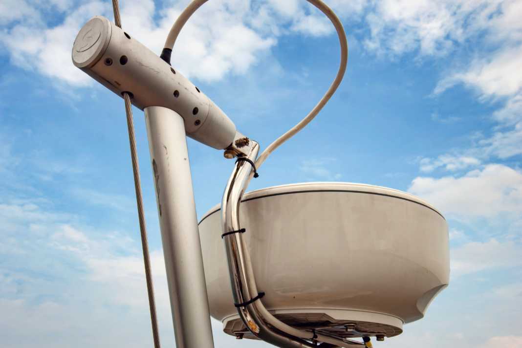
The smaller the lateral aperture angle, the better the azimuthal resolution. So-called slot radiators - freely rotating beam antennas, also known as "open array radar scanners" - are fundamentally superior in this respect to the radome antennas (dome antennas) popular on sailing yachts. Another factor is the size of the antenna: the larger the antenna, the smaller the horizontal aperture angle.
For some time now, attempts have been made to counteract this with computing power. Targets reflect across the entire width of the beam, but not with a uniform energy density.
Such factors can be taken into account in digital target separation in order to computerise the radar image. Corresponding digital signal processors have also been used in more recent pulse radar systems. However, beam sharpening only works to a certain extent - the result depends on the initial value, which is still determined by the antenna size. The latter therefore remains an important selection criterion.
Adaptive transmitters are also widely used today, which automatically adjust to certain environmental conditions and recognise typical target characteristics - for example, flocks of birds or bad weather fronts. Interference from swell and rain is also automatically recognised and filtered out. If you no longer want to experiment with input amplification ("gain"), swell and rain filters yourself, you can leave this to the device. This means that significantly less experience is required to obtain a usable display and the operation of the systems has become much simpler and therefore safer.
Functions such as Doppler and MARPA
Some pulse compression radars also take the so-called Doppler effect into account. This is known from sound effects - for example, a siren sounds different when it is approaching than when it is moving away from you. This is because the sound wave is either compressed or stretched. Something similar happens to the electromagnetic wave emitted by the radar when it is reflected by an approaching or receding target. In radars with a Doppler function ("Doppler radar"), these targets are highlighted in colour. Approaching targets are usually shown in red and receding targets in green.
The NXT models from Furuno all have this function, as do the Fantom radars from Garmin and the larger Halo radars from Navico (only the Plus version of the Halo 20). The Quantum radar from Raymarine is available with or without Doppler function (standard on the Cyclone). The target tracking function MARPA ("Mini Automatic
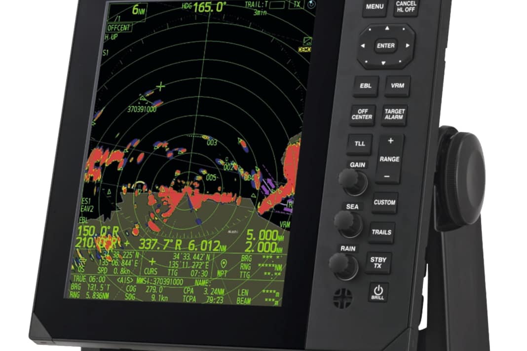
Radar Plotting Aid"), on the other hand, already existed for impulse radars. MARPA allows individual radar targets to be selected and tracked, with the electronics calculating the approach data - including how close the target will come (CPA = "closest point of approach") and the remaining reaction time (time to CPA).
Such sophisticated target tracking features require the connection of an electronic compass and compatible evaluation hardware. Meanwhile, the display of so-called trails is available on almost every radar - signal traces from previous antenna orbits that can be used to at least roughly deduce the echo displacement ("true trails" in turn require corresponding technology).
Compatibility of the components
With the stand-alone solutions that used to be common, you bought a coordinated package consisting of an antenna and matching "radar box". The latter can still be found occasionally - for example the FR10/12 models from Furuno or the R2009 radar control unit from Navico. In the meantime, however, multifunction displays (MFDs) have become established, which, in addition to their function as chart plotters, also function as radar screens. The actual radar system is a simple antenna unit (black box scanner). Merging the data in a control centre opens up interesting features such as radar image overlays on the electronic chart or AIS overlays on the radar image. As is usual with imaging sensors, the radar scanner is generally connected via Ethernet or WLAN - NMEA bus systems are no longer sufficient here. In most cases, proprietary standards are used so that, with a few exceptions, the radar scanner and MFD must come from the same manufacturer.
Nevertheless, finding the right combination can present a certain challenge. This is because, like all black box transducers, radar scanners are also dependent on their functions being supported by the analysing system. For example, although the Q displays, which are also offered by NKE, allow the connection of a Quantum radar scanner from Raymarine, the radar app on the displays only has rudimentary radar functionality. Features such as MARPA and Doppler radar are not included.
The respective interfaces must also be compatible. For example, Raymarine's Element display series does not offer a RayNet connection, which is used by the manufacturer's current radar scanners. A Quantum radar would therefore have to be purchased in the WLAN version in order to be able to connect it wirelessly. It is also worth taking a closer look at the other peripherals - for example, when it comes to a compatible compass for creating a north-stabilised radar image and corresponding target tracking functions.
Installation tips
If you want to be on the safe side here and don't want to spend hours delving into the depths of the relevant technical manuals yourself - which don't always answer all your questions - you should seek detailed advice before making a purchase and, in particular, have the compatibility checked.
In view of the impressive cost/performance ratio offered by modern pulse compression radar systems, there's really no getting away from the basic radar technology. Pulse radars are obsolete - apart from a few special cases, such as the Furuno DRS4W WLAN radar designed for iPad navigation or very range-intensive applications.
This is because, in addition to the antenna height (see box), the transmission power remains a limiting factor for the range. With a maximum power of ten watts, even a pulse compression radar will not reach far distances.
Another distinguishing feature is the rotation speed of the antenna, which determines the update rate of the radar image: the faster the antenna rotates, the more up-to-date the radar image. Short-term updating can pay off, especially for targets at close range. Some devices are also capable of displaying two ranges in parallel ("dual range").
However, this again requires compatible evaluation hardware. This applies all the more to MFD-side features such as alarm functions. And another tip: choose a display of sufficient size as the radar screen - on a 7-inch display, radar image evaluation can become a mouse cinema. Ultimately, it always depends on the overall system, which includes the choice of antenna position and mounting.


Function and characteristics of radar systems
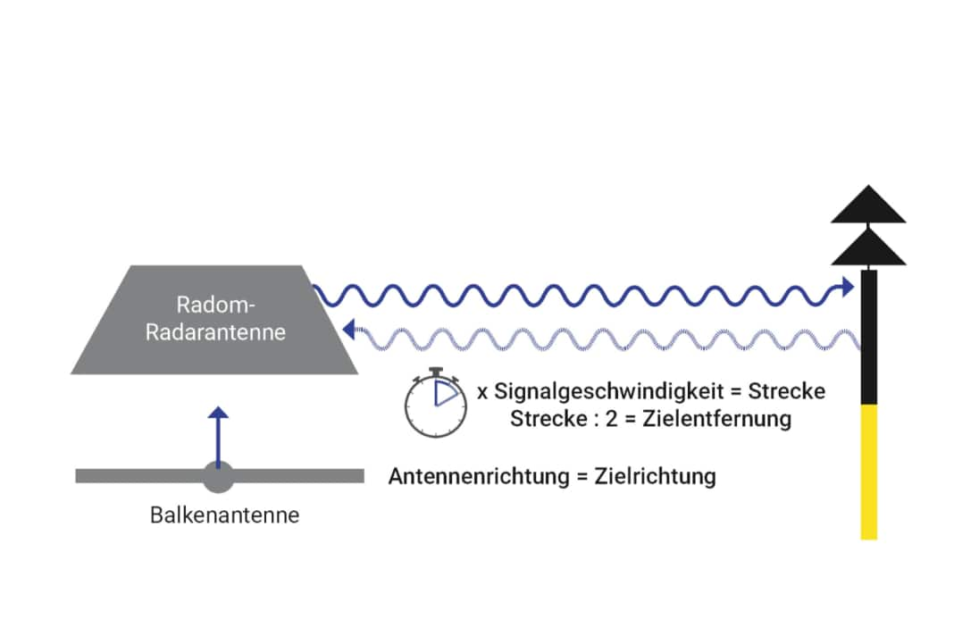
A radar antenna emits electromagnetic signals. If the radar signal is reflected by a target and returns to the antenna, the target distance can be calculated based on the time elapsed since the signal was emitted (the signal propagation time). The latter results from the propagation speed of the signals, which corresponds to the speed of light - i.e. around 300,000 kilometres per second or 300 metres per microsecond (millionths of a second, µs).
At the same time, the radar antenna is continuously rotated to scan the ship's entire surroundings. The direction in which the antenna is pointing when a reflected signal arrives provides the bearing to the target.
As the antenna is on board, all measured values refer to the location of our own yacht. The latter is at the centre of the radar display. If the yacht is underway, the antenna's own movement is included in the echo movements on the screen. The echoes of stationary targets (navigation marks, mooring lines) move across the screen at the speed of your own yacht in the opposite direction to your own course. Meanwhile, an echo display that remains on the screen is likely to come from a "fellow traveller" moving at the same speed in the same direction. In addition, the radar image is always aligned to the right-hand direction of your own yacht ("Head Up") - the top of the radar screen therefore corresponds to the bow direction. Bearings of targets are side bearings. If the radar unit is networked with an electronic compass, a north-stabilised alignment ("North Up") can also be realised. The echo movements remain relative movements, but the top of the radar screen is then north (bearings are north-related), which makes it easier to synchronise with the nautical chart. Another variant is the course-stabilised alignment ("Course Up") - it is similar to "Head Up", but without the radar image necessarily blurring in the event of steering inaccuracies (also requires a direction sensor).
The right antenna location
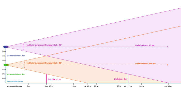
The vertical aperture angle of most radar antennas is around 25 degrees. It determines the distance from which the radar beams hit the water surface. The higher the antenna hangs, the greater this distance and therefore the greater the blind zone around the antenna. For example, a barrel a good two metres high could only be detected at a minimum distance of over 25 metres with an antenna height of eight metres - but at a distance of less than ten metres with an antenna height of four metres.
The antenna height also determines the range - the radar horizon. The theoretical range in nautical miles can be calculated using a formula in which the square root of the antenna height is added to the square root of the target height (both in metres) and the whole is multiplied by a factor of 2.23. If the target height is set to zero, the result is the distance of the radar beam. Here is another example: four metres antenna height results in a radar height of around 4.5 miles, eight metres antenna height pushes the radar height to around 6.3 miles. A cargo ship with a 20 metre high superstructure would be visible at a distance of around 14.4 nautical miles with the four metre high antenna, and at a distance of around 16.3 miles with an antenna height of eight metres. In any case, a semi-cardanic antenna mounting is recommended. Otherwise, when the yacht is heeling, the range is considerably reduced downwind, while close range detection deteriorates upwind.
