Navigation: GPS waypoint navigation - tips and tricks and common mistakes
Sven M. Rutter
· 17.07.2024
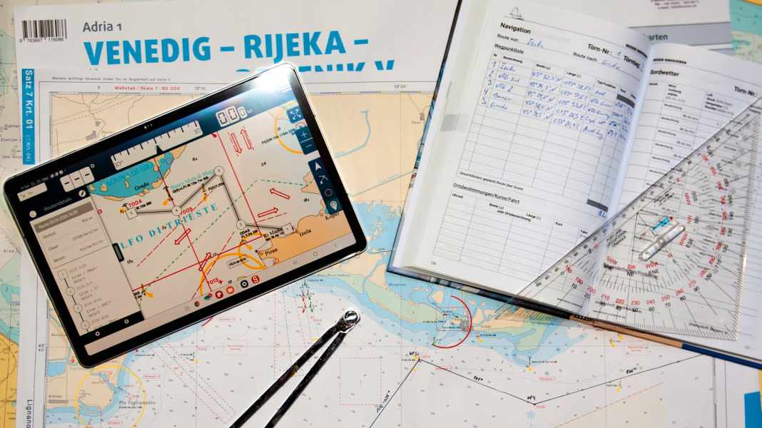
The use of GPS & Co has now become a matter of course for navigation, and hardly anyone gives it much thought. At the same time, the technology has continued to develop, which is why we now refer to GNSS (Global Navigation Satellite System) as a generic term for the various satellite navigation systems available.
Navigation series
When working with GNSS devices on pleasure craft, there are still some challenges to overcome - from correctly interpreting the available data to mapping out the best route to the intended destination.
Babylon on the screen
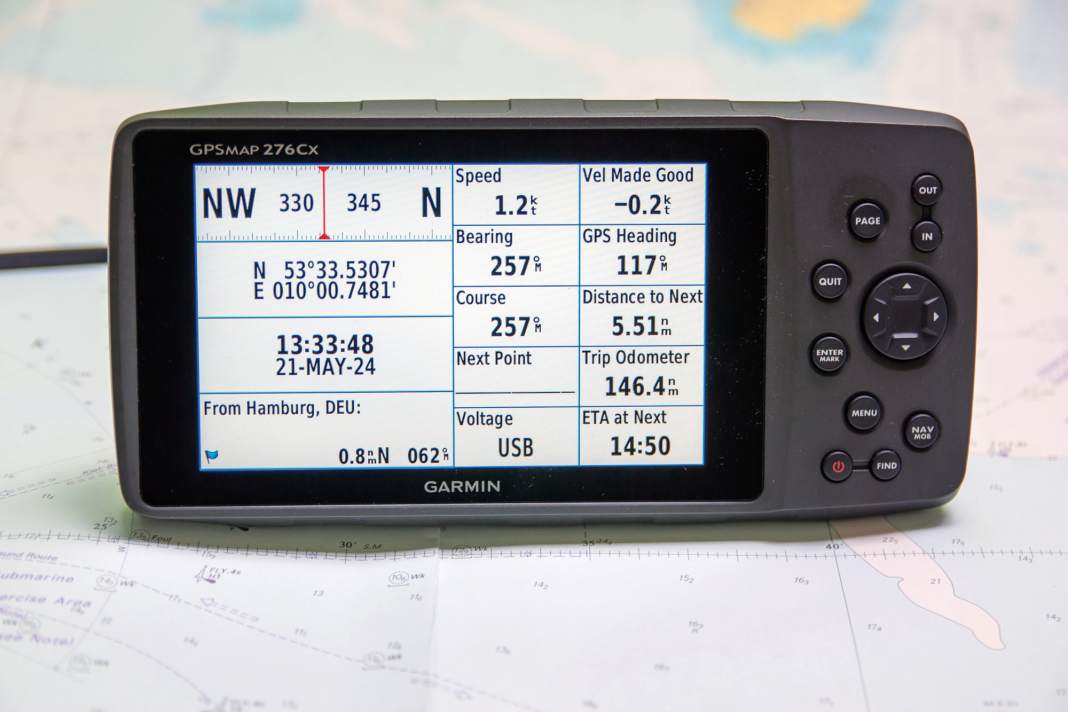
The first hurdle is the unambiguous categorisation of the numerous data provided. Unfortunately, even elementary values often have different designations in common recreational boating systems, and this applies all the more to their abbreviations. For example, a three-digit heading could either stand for the chart course or for the yacht's current direction of movement over ground or even for the direction to the next waypoint - which is not the same thing.
While we have largely equated the course over ground (KüG) with the chart course (KaK) in previous episodes, GNSS navigation requires a more differentiated approach. When we draw a course from the starting point to the destination on the nautical chart, we are talking about the intended course over ground. This chart course (KaK) describes the "desired course", so to speak, and is often labelled DTK (Desired Track) or DCOG (Desired Course over Ground) or simply CS for Course on GNSS devices.
On top of this, the GNSS device constantly determines - several times a second - the direction travelled by the boat over the ground. This value, usually output as COG for course over ground (KüG) and sometimes also as TRK for track, describes the yacht's current direction of movement. One could also speak of the "actual course".
You should also always bear in mind which sensors the displayed values originate from. For example, a three-digit heading value shown as Heading (HDG) cannot actually originate from the GNSS, as it has no relation to the boat's heading. An electronic compass must be involved here, as only this knows the current heading.
Differences between the respective course data provide valuable information about a possible lateral offset, and it is precisely one of the advantages of electronic navigation that these values are always available - you just have to know how to assign them correctly.
Speed without the hustle and bustle
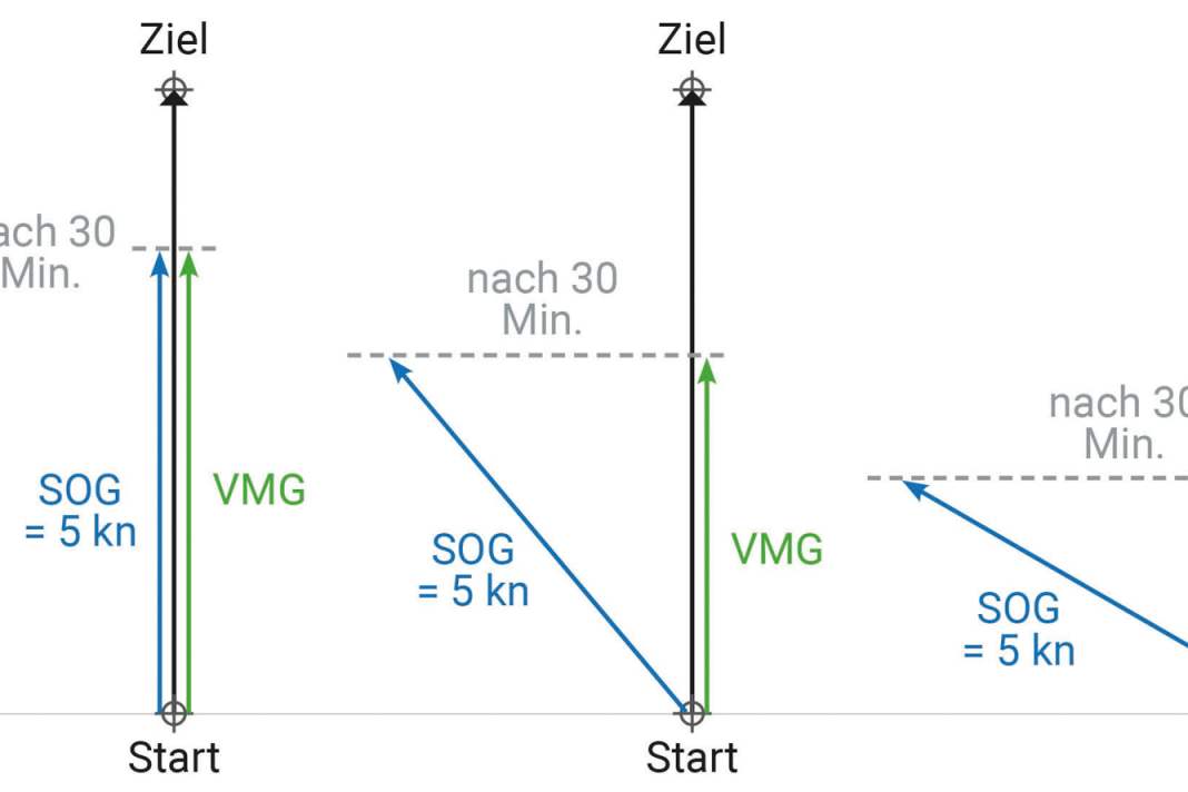


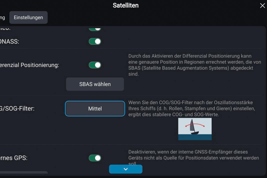
In addition to course values, the GNSS also continuously provides the current speed over ground, usually labelled SOG (speed over ground) or simply SP for speed. It is determined on the basis of the permanent shift in position in relation to time - in the same way as speed over ground (FüG) during coupling, but at much shorter intervals. The interval at which the course and speed information is updated can usually be set. This helps with hectic oscillating display values.
If a routing is in progress - i.e. a specific destination such as a waypoint has been set as a heading marker - the velocity made good to the destination is also determined, which is usually referred to as VMG (Velocity Made Good). It describes the speed at which the yacht is travelling towards the destination. If the boat deviates from the chart course, the VMG decreases because it is no longer travelling directly towards the target. The VMG is helpful when cruising in order to allocate hole and stretch bows. On upwind courses, it can help to find the ideal compromise between height and speed.
All data supplied by the GNSS naturally relates exclusively to the yacht's movement over the ground. For the search for the perfect sailing trim, the speed through the water (FdW) is often more relevant, which in turn requires a log. The same applies to the Power navigation.
Navigation is scouting


To benefit from all these functions, a route consisting of individual waypoints must first be programmed into the device. The waypoints are either defined on a paper chart and then their positions transferred to the navigation device or, in the case of plotters, set directly on the electronic chart.
The specific procedure again depends on the device, so you should familiarise yourself with the most important functions in advance: How are the individual waypoints put together in the correct order to form a route? How can a waypoint position be subsequently moved, how can an additional waypoint be added to a route, how can a waypoint be deleted from a route?
With plotters, it should be borne in mind that zooming in the vector maps commonly used there is equivalent to a change of scale. When zooming out, important content can disappear in favour of clarity. As with paper nautical charts, it is therefore advisable to work at the largest available scale when planning your route. To be on the safe side, every route marked out on a plotter should be "scanned" again with the cursor at the highest zoom level before casting off.
Waypoints should be set at any point on a planned route where a change of course is imminent or where special attention is otherwise required. This could be, for example, a flat spot that needs to be avoided but passed nearby, a restricted area next to the route or even a sea mark on the route so as not to cross it.
Most devices continuously display the remaining distance and journey time to the next waypoint. If necessary, the display fields on the GNSS/plotter display should be adjusted accordingly. In addition, a proximity alarm can often be set.
The approach buoy to the destination harbour as the last waypoint also makes it possible to calculate the estimated time of arrival (ETA). Meanwhile, setting the final destination as the sole waypoint harbours the risk of overlooking treacherous spots en route or missing necessary course changes.
Otherwise, the choice of waypoints is at the skipper's discretion: any chart positions can be defined as waypoints or real navigation markers such as navigation marks can be used. Many sports boat chart sets also contain waypoint recommendations for popular routes.
Leave nothing out of consideration when navigating


However, healthy scepticism is advisable when it comes to so-called autorouting functions. Especially as they are based on a limited database that may not take all relevant aspects into account - not to mention system-related inadequacies.
It is therefore advisable to consider the forecast wind direction and strength as well as the resulting courses to the wind when marking out the waypoints. After all, it is important to pass leeward coasts, sea marks and shoals at an appropriate distance to windward. The waypoint positions must be set accordingly. In the previous episode, we described how to calculate a suitable course ahead. However, this may be too high upwind so that the drift cannot be fully compensated for.
You should also consider any currents and the expected swell, for example in shallow areas or downwind of islands. Placing a waypoint where a ground or cross sea is to be expected could prove to be unpleasant - it is better to avoid these areas.
I have also got into the habit of writing down the waypoints of each day's route in a tabular list - good logbooks already have corresponding forms. This list not only contains the waypoint names and positions, but also the distances and map courses between the individual points. It not only serves as a backup in the event of an electronics failure, but also as a plausibility check of the values output by the GNSS.
During synchronisation, for example, it can be quickly recognised if the electronics are still controlling an "old" waypoint because it was passed too far away and the device has not yet switched to the new waypoint.
Like on the motorway
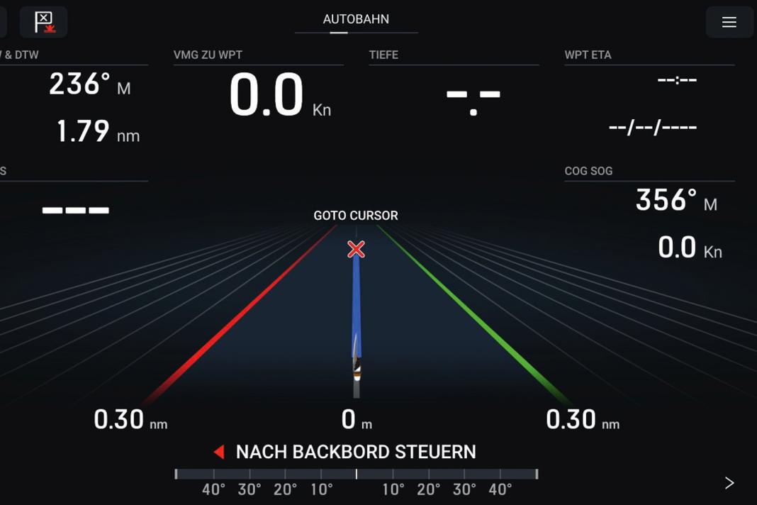


On the way, you can use the displayed values to check at any time whether everything is going according to plan. Among other things, this is done by constantly comparing the intended and the observed course over ground - i.e. between the chart course and the COG.
Most devices also offer a so-called highway display (also known as a course deviation indicator, or CDI for short). The centre line of the displayed road illustrates the chart course. If the yacht is off course, there is a lateral course error - a deviation.
The extent of this cross track offset can also be called up as a numerical value in nautical miles. The relevant XTE (Cross Track Error) or XTD (Cross Track Distance) information provides a good reference point for estimating a course ahead for an unexpected wind and/or current-induced offset. Some devices also provide recommended control values for a "heading correction".
It goes without saying that a comparison should be made with the chart each time the course is set so that you are not placed in dangerous terrain. If this threatens, a correspondingly sharp (possibly right-angled) up-course correction would be advisable.
Around the bend with the dog
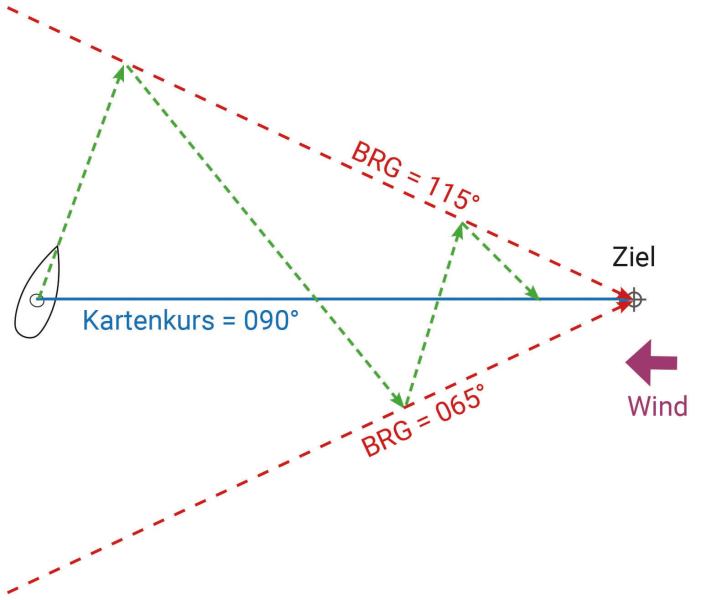
In addition, the bearing to the waypoint currently being navigated to is continuously provided as a bearing (BRG or BTW = Bearing to Waypoint). If the BRG indication deviates noticeably from the course over ground (COG), you may be tempted to correct the current heading to the BRG value - after all, the destination lies precisely in this direction. However, this would ignore the cause of the course deviation. As a result, the COG and BRG would diverge again after a short time.
Of course, you could then correct the heading again accordingly. With this approach, however, the movement of the yacht over the ground would gradually describe an arc - a so-called dog curve.
Background: If the cause of the course deviation is, for example, wind drift, the yacht will be driven further and further to leeward despite regular reorientation towards the target. In the end, the target would be exactly to windward. Unless, in the meantime, you have run aground on a flat that you actually wanted to avoid with the chart course.
It is better to work with the corresponding retention rates (see episode 3) so as not to deviate significantly from the map course in the first place. The BRG display provides a further useful reference point for corresponding loading values in comparison with the chart course. In addition, for example, bearings to the target (BRG) taken from the chart and also a maximum lateral course deviation (XTD) can be set as limit values when crossing (see graphics).
If the limit value is reached, the next turn is imminent. The virtual signposts that GNSS devices permanently provide in the form of all these values have revolutionised navigation at sea. However, their usefulness stands and falls with the person who defines the most important key data. Even the best technology cannot conjure up an ideal route from a haphazardly thrown-together route and carelessly set waypoints.
Control is better
With GNSS navigation, it is worth regularly checking the accuracy of the system. This is because it depends on the number and distribution of the satellites used.
Especially as supplementary systems such as the mobile phone network, which is used by smartphones and tablets to determine their location, or plausibility aspects that car navigation systems take into account (after all, they generally travel on roads and not through houses or across fields), only work to a limited extent at sea. Ultimately, every location in the water is also a possible ship location.
Almost every nautical GNSS device offers a status display that provides information on the number and spatial distribution of the satellites in use. It often consists of a graphical representation of the satellite distribution in the sky. If the GNSS satellites currently in use are concentrated in one direction, the accuracy is likely to be low - if they are evenly distributed, the position information will be much more reliable.
The influence of the geometric satellite arrangement is often also given as a mathematical value. This so-called DOP value (DOP = Dilution of Precision) is a dimensionless numerical value. The lower the value (e.g. below 3), the more reliable the position information can be estimated. High values, for example above 8, should be viewed critically. If several DOP values are displayed, the horizontal accuracy is decisive for nautical navigation (HDOP = Horizontal Dilution of Precision).
One cause of unfavourable satellite distribution may be lateral antenna shadowing. Perhaps someone is sitting in front of the GNSS antenna mounted on the stern, or the boat is sailing along a steep coast. In the event of permanent shadowing, a different antenna position or the connection of an external GNSS antenna should be considered, depending on the installation on board.
While you're at it, you can also take a look at the GNSS system configuration. If the device supports satellite-based augmentation systems (SBAS), such as the European Egnos, this function should be activated. The parallel use of different GNSS such as GPS, Galileo and Glonass can also pay off. This can also often be configured individually. And, of course, the map datum (geodetic datum, e.g. WGS 84) of the GNSS device and the map material used should match.
