- Navigation series
- Where, when and how fast
- Central formulas of dead reckoning
- Cutlery removal
- Misdirection: Deviation due to compass
- How the exchange rate conversion works
- Pre-coupling and co-coupling
- If the logger fails
- Calculate current declination
- Checking the magnetic compass deflection
Navigation series
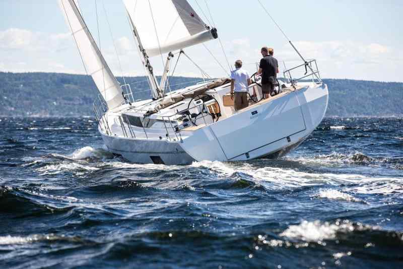
As already stated in the previous episode, you need at least a rough idea of where you are at sea to determine your location without a satellite navigation system such as GPS & Co. For this purpose, permanent coupling during the journey has proven its worth. For centuries, this method was the only way to determine the approximate location of a ship at any time. Without visible reference points, for example on the open sea with an overcast sky or reduced visibility, there was no other option.
The dead reckoning method is simple. The yacht's movement, deduced from its course and speed, is transferred to the nautical chart to determine where it should be at a certain point in time. This is done by plotting the course steered since the last known location of the ship. The distance travelled since the last location was determined is plotted on this course line. Its length is calculated from the logged speed in relation to the elapsed time (see formulas).
Where, when and how fast
The result is the so-called coupling location. It is generally labelled with a horizontal line on the course line and the abbreviation "OK" (an observed location, on the other hand, has the abbreviation "OB" and is circled). The current time is also entered so that it can be used later for further coupling.
The methods and formulas used for pairing are also suitable for making predictions. For example, advance coupling can be used to determine when you will arrive at your destination or the next waypoint. This Estimated Time of Arrival, or ETA for short, is calculated from the distance to the destination in relation to the speed of the yacht.
If the distance between two known ship locations is set in relation to the time elapsed between the locations, the average speed of the yacht over this distance is obtained. In long-distance sailing, for example, the daily average speed can be calculated using the Etmal (distance travelled in 24 hours).
Debit and credit
In contrast to an observed location, which is based on a measurement such as a cross bearing, a radar bearing or GPS, the determination of location using couplers is subject to a variety of uncertainty factors.
Firstly, there is the speed, which may have fluctuated a little over the course of the journey. If it is read from the log, it is also the speed through the water (FdW) - not the speed over ground (FüG). However, the movement of the yacht over ground is decisive for an accurate ship location on the chart. If the current is travelling with the yacht, it will move faster over the ground than through the water; if the current is moving against it, it will move more slowly.
Such uncertainties also arise for the direction in which the yacht has moved: Apart from any steering inaccuracies, wind drift and current offset can cause the course over ground (KüG) to deviate considerably from the steered course.
Coupling always represents a target and not an actual situation: The yacht should be in the coupling location - but it does not have to be.
Central formulas of dead reckoning
- Distance: d (sm) = (v (kn) - t (min.))/60 or d (sm) = v (kn) - t (hr.)
- journey time (ETA): t (min.) = (d (sm) - 60 )/(v (kn))
- Speed: v (kn) = (d (sm) - 60)/(t (min.) ) or v (kn) = d (sm) : t (hrs.)
Cutlery removal
If there is another chance to determine an observed location, this position may deviate significantly from the assumed coupling location for the same point in time. This deviation is referred to as the "cutlery offset" (BV). It is specified as the direction and distance from the OK to the OB (from the "wrong" to the "right", for example: BV = 155°/1.5 nm).
The displacement of the mast provides valuable information to detect an unexpected current shift or increased wind drift and to consider how far ahead should be kept after wind and/or current luv in future. If the ship is making much slower progress over ground than expected, the route planning may need to be adjusted in order to reach the destination in daylight.
Misdirection: Deviation due to compass
In order to achieve useful results when coupling, an attempt should be made to minimise the offset of the cutlery. This requires conscientious course loading, in which all conceivable influencing factors are taken into account.
This applies to the wind offset and the prevailing current as well as to typical compass errors. The latter result in the course read from the steering compass not matching the actual movement of the yacht over ground, even in current-free waters and without significant wind drift.
One reason for this is misalignment: while the nautical chart is orientated to true north (rwN) - i.e. the direction to the geographic North Pole, where the meridians (longitudes) converge - a magnetic compass is orientated to the earth's magnetic field.
Simplified, one could also say that it is aligned to the magnetic north pole, where the field lines of the earth's magnetic field enter the earth's surface vertically (whereby the north needle of a magnetic compass is strictly speaking aligned to the southern magnetic pole, which is therefore actually located there - but we will stick to the usual term here). This direction is referred to as true north (mwN).
The misalignment must be taken into account
As the geographic and magnetic poles are not at the same location, there is a greater or lesser angle between the two north directions, depending on the location - the magnetic declination (MW).
If our yacht is travelling exactly on a northerly course according to the compass, we cannot be sure that we are also travelling exactly parallel to the meridians on the nautical chart.
This angular difference must be taken into account. And as it is not the same at every location on earth, the extent of the deviation depends on the sea area in which we are currently travelling - especially as the earth's magnetic field is not completely uniform.
Information on the local bearing can be found on the nautical chart. They are usually noted in a printed compass rose. Sometimes you will also find framed boxes with the direction information. If there are several of these on a chart, you should use the nearest one as a guide.
The values always refer to a specific year, as the magnetic north pole moves. While it was located in the north of Canada towards the end of the 20th century, today it has set course for Siberia. For this reason, the misalignment information may have to be converted to the current year (see below).
Deflection or deviation on steel yachts greater
In fact, the steering compass is not orientated to true north, but to magnetic compass north (MgN). This direction only exists on board. This is because there are also numerous magnetic influences on board that deflect the compass - for example metal components and especially iron parts, but also electrical cables.
The boat-specific deviation of the north direction of the steering compass is referred to as deflection or deviation. It is naturally particularly large on steel yachts, but even on GRP boats, the engine block and alternator, the steering gear, the navigation electronics, the radio, external loudspeakers, metal objects stowed away in the cockpit and even the mobile phone in the helmsman's pocket can throw the compass off course without it being noticeable.
The deviation also varies depending on the course. Sometimes the bow direction causes the ship's magnetism and the earth's magnetism to reinforce each other, in other cases it causes them to cancel each other out - to put it simply. And depending on the direction in which the deflection occurs, it has either a positive or a negative sign.
To get a grip on deviation, all magnetic objects that could influence the compass should be banned from its vicinity. The influence of permanently installed components on board can be determined by means of a compass check (see box on page 30).

Ideally, a deflection table for the steering compass was created on this basis, which shows the correct deflection value of the ship for each magnetic compass heading.
Sometimes there is also a so-called steering table with adjusted deflection values in the event that a chart course taken from the nautical chart is to be converted into a heading.
How the exchange rate conversion works
This brings us to the correct course conversion. Similar to the bearing conversion (see previous episode on terrestrial positioning) a calculation scheme that works from top to bottom - from the "wrong" to the "right", with the latter being the right direction:

The signs to be used are also based on this calculation direction. If an rwK is to be converted into an MgK, the calculation must be performed from bottom to top with the sign reversed. The sign for the deflection is taken from the deflection table or the control chart together with the relevant degree value. The following applies to the deviation: An easterly MW always has a positive sign, a westerly MW a negative sign.
With this calculation, the so-called misdirection (Fw) - the sum of Abl and MW - has already been ruled out as the cause of a possible mounting offset. What remains are wind drift and current offset - their consideration will be explained in the next instalment of this series.
Pre-coupling and co-coupling
Coupling work can prove useful in practice in many ways. For example, pre-coupling - i.e. the prior entry of all planned courses in the route with degree and distance on the nautical chart - provides a good plausibility check for the data output by the navigation electronics. This allows errors in the programming or in the system to be recognised quickly.
It has proven to be a good idea to regularly note the steered courses and logged speeds in the logbook to ensure continuous docking. As a reliable docking location depends on the reliability of the movement data, it is advisable to make a corresponding entry in the logbook and nautical chart at least every time there is a change in course or speed, for example when the wind dies down or picks up. If frequent manoeuvres are planned, navigation in the area being sailed is
area or if you have to deal with very changeable conditions, shorter time intervals are recommended than for a long, straight stroke with a constant breeze over the open sea.
Just give it a try. Coupling is fun and leaves impressive patterns on the nautical chart. I like to use such charts later as wrapping paper, which always goes down well. And if the electronics on board should ever fail, the conscientious pre-coupling and co-coupling will also prove to be a welcome gift.
If the logger fails
Since the logger is generally also dependent on a functioning on-board electrical/electronic system, an alternative speed measurement method is required in the event of a technical failure. The so-called railing log could help here. This involves throwing something buoyant - an apple, for example - overboard at the bow of the yacht and stopping the time until the object reaches the stern. A ship travelling through the water (FdW) at one knot (kn) travels 0.514 metres in one second (1 kn = 1 nm/h = 1,852 m/h = 1,852 m/3,600 sec = 0.514 m/sec). This distance is referred to as the meridian tertie (MT), which in practice can also be rounded to 0.5 metres. In principle, the following applies: MT per second = nautical miles per hour (= kn).
The only thing left to do is to determine the distance the apple has travelled from the bow to the stern. If the yacht is 12 metres long, this corresponds to 24 MT (12 m : 0.5 m = 24). If the apple has taken 6 seconds to do this, the yacht is travelling through the water at 4 knots: 24 MT in 6 seconds = 4 MT per second, i.e. 4 knots.
Calculate current declination
The magnetic variation (MW) describes the angle between true north (rwN) and magnetic north (mwN). Information on the local MW can be found on the nautical chart in degrees and minutes. In addition, there is the direction: E (East) for an easterly and W for a westerly MW.
The reference year and the annual change are also shown in brackets. If the change is in the same direction, it is added, otherwise it is subtracted.
An example: The specification 3° 16' E 2022 (12' W) means a MW of 3° 16' East in 2022 with an annual change of 12' West (W). For the year 2024, this results in: 3° 16' E2 - 12' W = 2° 52' E. Whereby for the course charging is always rounded to whole degrees, i.e. to 3° E.
Checking the magnetic compass deflection

The steering compass must be checked accordingly in order to take the deflection (deflection) into account when setting the course. A compass check is particularly advisable if the ship's magnetism has been altered - for example by additional equipment, conversions or technical installations.
The simplest option is to compare it with a secured bearing line (see previous episode). If, for example, I am standing with my yacht exactly on a leading light line for which a direction of 151° is indicated on the nautical chart and align the bow with this line, then my true course (rwK) corresponds exactly to this value. The rwK must now be converted into a misdirectional course (mwK) using the local misdirection (MW) (rwKMW = mwK). This is compared with the magnetic compass heading (MgK). If the steering compass shows a deviating value, the following applies: mwK -MgK = Abl.
As an alternative to such a deck bearing, you could also take a bearing of the fires of the leading light line that are under cover using the steering compass without aligning the bow with it. The following then applies: mwP -MgP = Abl (the mwP again corresponds to the 151° corrected by the MW, the MgP is the magnetic compass bearing). The whole thing also works if you take a bearing on an object with a known position from a secure location, for example directly next to a navigation mark on the chart.

The same procedure is used when drawing up a deflection table for a deviation dolphin. Since the position of the dolphin is known, a reliable true bearing (rwP) is obtained for each landmark also shown on the chart, which is converted into a mwP. Now the yacht is turned around the dolphin and a bearing of the landmark is taken via the steering compass after every 10 degree course change. In this way, the deflection can be determined for each course - at least in course steps of 10 degrees; for intermediate values, interpolation may be necessary. Alternatively, a bearing disc could also be used, the lateral bearing of which is then added to the respective compass heading to form an MgP.
The values are entered in a corresponding table. Some also create a deviation curve and an additional control panel - but we don't want to make things too complicated at this point. It is also possible to have the compass compensated by a qualified specialist.

Sven M. Rutter
Freier Mitarbeiter