Technology: Making the most of the radar unit on board - a detailed guide
Sven M. Rutter
· 25.09.2025
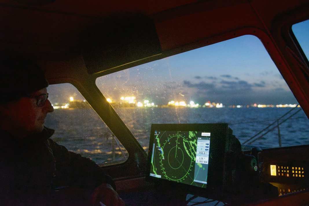


The technical development of yacht radar systems has made a quantum leap in recent years. Modern devices are less energy-hungry and produce less radiation exposure than their predecessor generations. They also provide detailed images even with a moderate antenna size. There are also innovative additional functions, such as Doppler radar, which automatically detects approaching targets and highlights them in colour.
That is also interesting:
Many parameters that previously had to be adjusted by hand can now be preselected automatically by modern systems. Nevertheless, it takes a little practice to orientate yourself on the radar image. Due to their special operating principle and technical compromises, yacht radar systems sometimes provide a rather unconventional image of the surroundings. The navigator on board should be familiar with these peculiarities and typical misrepresentations.
A radar is not an X-ray machine
One of the main advantages of radar is that you don't have to manoeuvre blindly in uncertain weather. But there are limits to what you can see. After all, the functional principle of a radar device is based on the fact that the emitted signals are reflected. Anything that is capable of reflecting the signals forms an impenetrable wall for the radar.
This is why, for example, land areas behind a raised coast appear as water areas. The radar does not receive any signals from there, so from its point of view there is nothing there. As a result, coasts are usually only displayed as narrow strips. The same problem arises with bends and indentations in the course of a river or coastline.
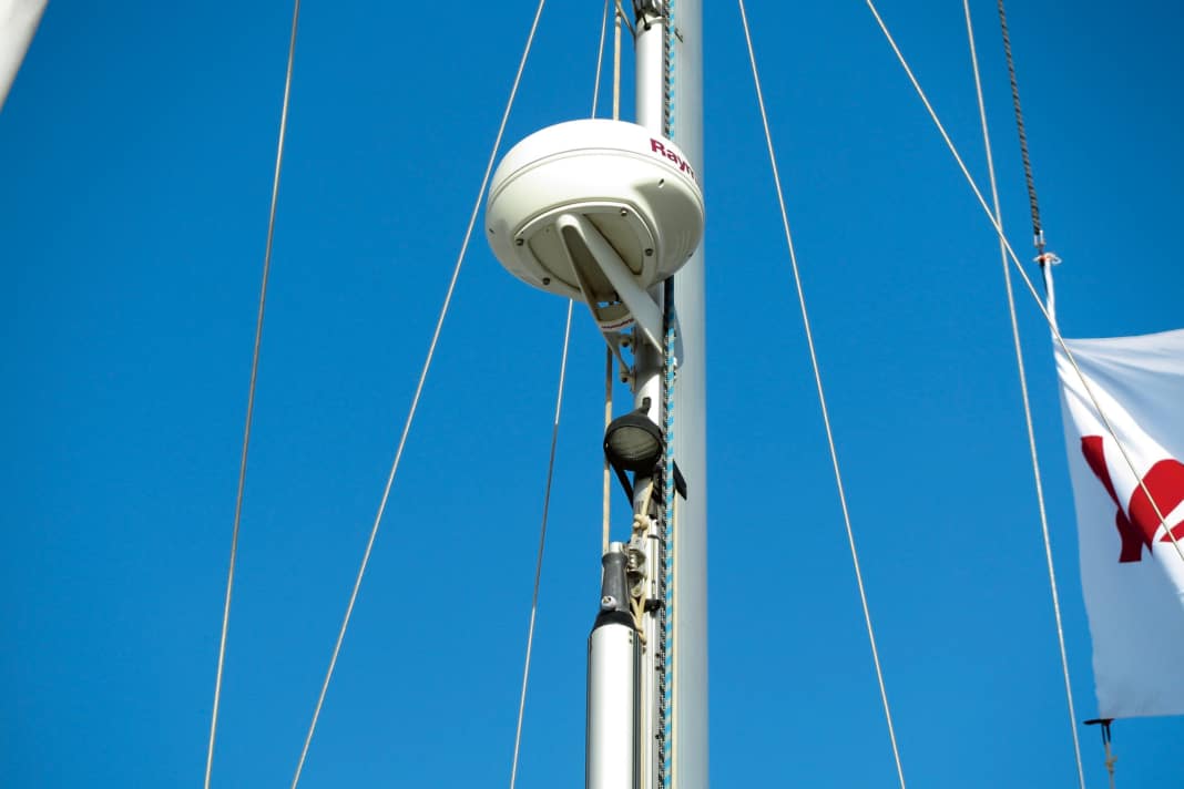
On-board installations in the radar's radiation range can also cause blind spots, such as the mast profile. The direction and extent of such shadowing must be taken into account when analysing a radar image.
Viewing area, targets, filters


Good and bad targets
How clearly a target is depicted in the radar - i.e. its echo size and signal strength - depends on its reflection properties. The material and size of the reflective surface play a decisive role here. Conductive materials such as metals reflect better than wood or plastic, including GRP. A steel barrel therefore provides a clearer echo than a wooden dolphin.
Large targets are also able to reflect a large proportion of the emitted energy. Especially as the echo spreads out further and further with increasing distance. A huge container ship is therefore almost impossible to miss on radar, while yachts only generate relatively weak echoes at a certain distance due to their low freeboard height. Added to this is the angle of the reflective surface. To be detected, the radar signals must be reflected back in the direction of the transmitting antenna.
This requires a reflective surface that is as vertical as possible. For this reason, flat beaches are sometimes not detected, but only the dunes or dykes behind them. Slopes deflect the radar signals in other directions. Curves cause scattering.
This also limits the reflectivity of aluminium rigs: They are usually rounded at the leading edge, while they are covered aft by the mainsail. This leaves only the sides as an efficient reflective surface - but only if the mast is vertical.
In a radar reflector, on the other hand, mirrors ensure reflection in the output direction thanks to multiple reflection. However, a clear echo requires sufficiently large mirrors.
Out of the snow flurries
At the same time, the radar detects many things that should not be displayed at all. We are talking here about interference. In order to obtain a usable radar image, the sensitivity must first be adapted to the prevailing conditions. This is done using the so-called amplification, which is labelled "gain" on most devices, which can be translated as "gain" in the broadest sense.
This gain consists of an increasing number of echo indications when the gain setting is increased. By increasing the sensitivity, however, false echoes are also increasingly detected. At some point, these threaten to overlay the radar image. This is referred to as snow because the image is reminiscent of a dense snow flurry. If the gain setting is reduced again, the interference gradually disappears from the screen.
The trick is to find a setting that minimises interference on the one hand and still captures weakly reflective targets on the other. This requires some sensitivity. The setting should also be checked regularly.
Some devices also have a setting option for colour gain (CG). However, this has nothing to do with sensitivity. This is about how clearly differences in signal strength are emphasised - for example in the form of corresponding colour gradations.
Swell in the radar image
The water that surrounds us also provides a conductive surface. Nearby waves in particular are often at a good angle for reflection and are also able to reflect back sufficient energy for detection. This results in numerous false echoes in the immediate vicinity of the ship.
This is where the so-called sea clutter comes into play - usually labelled "Sea Clutter" on the device side. The abbreviation STC for "Sensitivity Time Control" is also commonly used. In simple terms, this means that echoes from signals that have been travelling for a long time and have therefore covered long distances are amplified. Echoes from nearby targets with a short signal transit time, on the other hand, are attenuated. However, other weak targets at close range can also be affected by this attenuation - for example wooden or fibreglass boats. In heavy seas, they may no longer be detected by ships with a high sea state filter.
Operating modes for rain, swell and shipping traffic


Radar in the rain
A dense shower represents an almost impenetrable barrier for a conventional X-band radar. Any approaching bad weather fronts can be easily recognised on the radar. However, the wall of water also obscures everything inside and behind it.
Rain clutter, which is often labelled "Rain Clutter", provides a remedy. Sometimes you also come across the abbreviation FTC for "Fast Time Constant". In simple terms, this is about recognising clear fluctuations in the received echo signals. Echoes that all deliver an almost constant signal are attenuated or cancelled out. After all, every raindrop reflects similarly well or poorly to its neighbours.
Turning up the rain filter raises the overall tolerance threshold for distinguishing echo signals. And as rain does not have particularly good reflective properties, other weak reflective targets can also fall victim to the filter. Yachts therefore sometimes sail "under the radar" even in the rain.
Modern, adaptive radar systems usually provide an automatic function for the aforementioned settings. Thanks to sophisticated target evaluation, they are able to identify the characteristics of typical misrepresentations and automatically adjust the relevant settings.
In practice, there is nothing to stop you from using the auto setting to get started. However, in order not to miss any weak targets, the radar display should be checked from time to time with changing settings. Occasional readjustment is helpful for this.
The right modus operandi
Current systems also offer a choice of different operating modes to adapt the device configuration to specific situations and tasks. These can relate to the environment, such as sea passages ("Offshore"), coastal areas ("Coastal") or in the harbour ("Harbour"). There are also operating modes that focus on specific target types, such as recognising sea marks ("Buoy"), birds ("Birds") or weather phenomena ("Weather").
The Offshore operating mode assumes a certain level of sea reflections, while the Harbour mode takes into account corresponding reflections from land. The Buoy mode is optimised for detecting small targets, while Birds and Weather are designed for the typical reflective properties of flocks of birds and precipitation respectively. The former is particularly interesting for fishermen.
The operating modes depend on the radar scanner. This requires an adaptive receiver with high resolution and, in some cases, a Doppler function. In addition, the display software must support these functions.
Following your nose
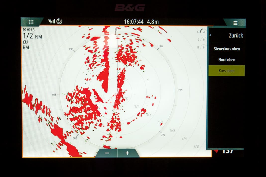
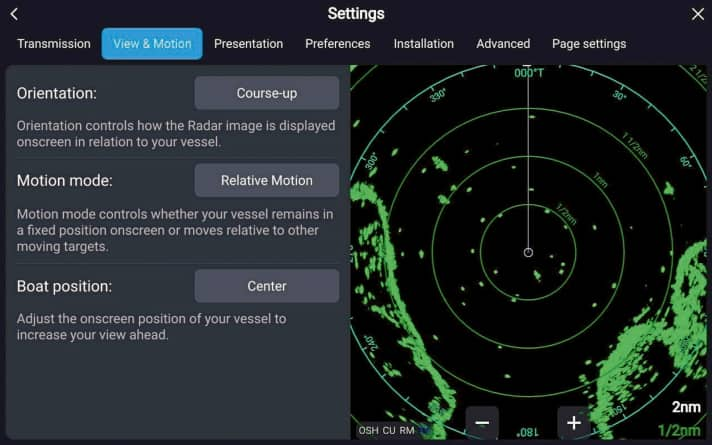
If the multifunction display (MFD) used can access data from an electronic compass, the orientation of the radar image can also be varied. The standard is a display orientated to the right, also known as "Head Up" (HU). In this case, the leading line in the radar image always points vertically upwards, which corresponds to the bow direction of the yacht. This facilitates collision prevention, as the orientation is similar to the perspective of a lookout on deck: who is approaching from port, who is approaching from starboard, who is overtaking, who are you closing on?
The disadvantage is that the radar image is easily blurred by steering inaccuracies. This is because if the bow swings back and forth, the radar image is also constantly shifted. The "Course Up" (CU) setting offers a good alternative. Here, the radar image is aligned with the desired direction of travel (target course) - with the advantage that it is stabilised with a comparable perspective.
This requires an electronic direction finder, which also applies to a north-facing display. North Up (NP) facilitates synchronisation with the chart when navigating under radar.
Regardless of the orientation, the radar always provides a relative representation, known as "relative motion" (RM). "True Motion" (TM) would require a suitable overall system. This means that with RM, the movement of your own yacht is included in the movement of the echoes on the screen. The antenna moves with it. Accordingly, stationary targets such as navigation marks move across the screen at the speed of your own yacht parallel to the advance line.
This in turn corresponds to the perspective of a lookout in the cockpit. And as with the lookout, every stationary bearing in the radar also means a risk of collision. This is always the case when an echo moves towards the centre of the radar display, where our antenna is located.
Positioning by radar
In addition to collision avoidance, the radar also enables precise location determination. For this purpose, the bearing and the distance to objects with a known position are determined. This results in bearing lines that can be transferred to the nautical chart.
Bearings can be measured using the cursor or the electronic bearing ruler, which has the abbreviation EBL for "Electronic Bearing Lineal". Whether the degree value displayed can be transferred directly to the nautical chart always depends on the reference direction. If it is followed by an R for "relative", it is a lateral bearing to which the current course must be added.
Some devices also measure lateral bearings in semi-circles - then the degree value is followed by a P for "Portside" (port) or S for "Starboard" (starboard).
While lateral bearings can be realised on any device, north-related values require a connected electronic compass. The bearing value is then followed by a T for "true" or an M for "magnetic". For a bearing line, we always require a true bearing. This in turn assumes that the compass has been calibrated in order to know the course-dependent deflection (Abl). In addition, the system must have the corresponding location data to take into account the location-dependent deviation (MW).
Distance measurements using the variable range marker (VRM) are less complicated. This can be used to directly create a circular standard line in the radius of the measured value.
Electronic monitoring
To facilitate collision avoidance, many radar devices offer automated target tracking - in the form of the MARPA function (Mini Automatic Radar Plotting Aid). If an echo is marked as a MARPA target, the device calculates the expected maximum approach, the CPA (Closest Point of Approach), as well as the remaining reaction time TCPA (Time to Closest Point of Approach).
In most cases, the movement vector of the target is also displayed on the radar image. The navigator can also call up certain movement data such as the course and speed over ground (COG/SOG). There is also a so-called target list, in which the marked targets can be sorted according to distance or danger.
Another prerequisite for using MARPA is a connected electronic direction sensor and an MFD that supports this function. A proximity alarm can often also be set if a MARPA target threatens to fall below a certain minimum distance.
Freely definable alarm areas, known as Guard Zones, are also primarily a software function. They can be placed around your own ship at a certain distance and in a defined direction. If a target enters the zone, an alarm is sounded.
Just do it
To practise, you should try out the radar functions when visibility is good. Nothing can be fundamentally changed if the auto function is activated again afterwards. Trying it out familiarises you with the menus and peculiarities so that the system is a real help in poor visibility.
Instructions: How to access the filter functions
While there is a corresponding button for all important settings on standalone radar devices, you have to navigate through the menu on multifunction displays (MFDs), which also serve as chart plotters. Depending on the device, there are different branches to take. There are also different designations.
To avoid confusion caused by creative translations, it is best to familiarise yourself with the English-language menu navigation straight away. In the following, we will show you how to access the most important filter functions on common systems. If your own product is not among them, the operating instructions will help.
Raymarine MFD with current Lighthouse operating system (e.g. from the Axiom series)
There are two ways to access the filters: either tap on the three horizontal lines (menu) at the top right and then select "Adjust sensitivity". Or click on the stylised sliders at the bottom left. Then "G" for "Gain", "R" for "Rain" and "S" for "Sea" appear at the top right. Pressing on the relevant letter opens a slider for the setting. Alternatively, the "Auto" function can be activated by ticking the corresponding box. On older E-series MFDs, the relevant softkey ("Gain") must be pressed to call up the aforementioned functions.
Current Garmin MFDs of the GPSMAP series
Here, icons for "Gain", "Sea Clutter" and "Rain Clutter" are displayed on the left-hand side of the screen in the radar app, which also show the corresponding setting in per cent. The respective setting can then be changed by tapping on it. Alternatively, you can access the functions by clicking on "Options" at the bottom right of the screen.
Zeus MFDs from B&G
These devices also have icons with percentage values. They can be found at the top right of the image, again labelled "G" for "Gain", "R" for "Rain Clutter" and "S" for "Sea Clutter". Others: An analogue picture can be seen with current Simrad MFDs (for example from the NSO series). With a Furuno TZ-Touch3 MFD, however, you have to call up the pop-up menu (click on the screen) and then select "Radar settings".
